4 Bit Counter Schematic
4 bit binary counter 8051 counter segment display bit using interfacing schematic program implementing Counter bit verilog flip synchronous using flop diagram circuit flops gates signal output stack
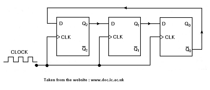
The 3-bit counter circuit. | Download Scientific Diagram
4 bit binary counter 4-bit counter 3 bit synchronous up counter on 14 th
4 bit down counter
Counter bit flip using binary flops circuit output q3 finalCircuits binary Circuit design of a 4-bit binary counter using d flip-flops – vlsifacts8 bit counter verilog.
Counter bit code johnson verilog vhdl circuit diagram example shown below testbench ckt tricks coding digital tips statesCounter verilog bit schematic javatpoint hardware Binary counter circuit diagram using ic 74hct40404-bit ripple counter.

Circuit design of a 4-bit binary counter using d flip-flops – vlsifacts
Counter verilog schematic bit hardwareCounter bit schematic using porting pcb issues when logic circuitlab simulate created stack Solved a two-bit counter has the following circuit diagram.Circuitverse counters synchronous binary bcd 4bit truncated sequence.
Circuit counter binary diagram ic explanation working circuitdigest3-bit binary counter Digital logicBit circuit counter two has diagram solved following output transcribed problem text been show draw.
4-bit counter
6 bit counter schematics.The 3-bit counter circuit. Counter binary bit electronics projects tutorial mini iv circuitMultisim counter synchronous.
Verilog coding tips and tricks: verilog code for 4 bit johnson counterVerilog 4-bit counter Counter circuitlab bit circuit descriptionCounter bit binary flip down using circuit flops diagram schematic circuits jk 555 timer three only asynchronous integrated gr next.

Counter bit state diagram flip binary using circuit flops table truth draw construct let
Counter bit schematic repeat clocks each after digital circuit engineering logic circuitlab created using stackCounter binary bit led matrix circuit diagram 5x7 display schematic figure block 4bit breadboard Counter bit down circuit diagram digitalCounter flop binary.
Binary outputs circuitDigital logic Bit counter schematicsCounter bit binary pcb circuit flip using ff layout practical multisim androiderode simulation flops.

Build a 4-bit binary counter with 5x7 led matrix
Implementing a 4-bit counter using an 8051 and interfacing it to a 74 bit binary counter Counter bit ripple circuit electronics circuits simulator simulationCalculator routing node.
Pcb design practical-4 bit binary counterCircuit analysis .


4 bit Binary counter

PCB Design Practical-4 Bit Binary Counter

Circuit Design of a 4-bit Binary Counter Using D Flip-flops – VLSIFacts

4-bit counter

Solved A two-bit counter has the following circuit diagram. | Chegg.com

Verilog 4-bit Counter - javatpoint

The 3-bit counter circuit. | Download Scientific Diagram